10 Determining the capture window of a capture card
10.1 Introduction
In this section, It is assumed the reader is familiar with the concept
of video lines, size, aspect ratio and active picture area. If not,
please read section 3 first. This is
just a quick guide on how to determine which part of a video line is
captured by a video capture device.
The official numbers, according to Rec. ITU-R BT.470-6, for the
active part of a video line are:
For PAL, a whole line takes 64 µs and the active part is 52.0 µs, but
may lie between 51.7 and 52.0 µs.
For NTSC, a whole line takes 63.555 µs and the active part is 52.66 µs,
but may lie between 52.46 and 52.86 µs
(Actually, for NTSC there are a number of standards which all differ
slightly on the size of the active area and even on how to measure it.
But the number used in Rec. ITU-R BT.470-6 seems to be the one most
widely used when dealing with digital video formats.)
Unfortunately, manufacturers of capture devices have different ideas
about how much of the total signal actually should be captured.
Vertically, all devices capture 480 (NTSC) or 576 (PAL) lines and
resize to the required vertical size afterwards. The only
exception to this is when vertical sizes below half these numbers
are captured. In that case, capture devices simply drop every second
field and resize the remaining field if needed. Because of this, you
only need to determine the horizontal width of the capture window.
A capture device will typically sample the whole video line at a fixed
high sampling rate, crop off all pixels which fall in the horizontal
blanking area and resize the remainder to whatever horizontal size was requested by the user. (Actually, the whole line is
resampled to a lower size and cropping horizontal blanking data
is the last step, but the result is the same). The areas to be cropped
are set to a fixed percentage of the whole line by the driver and
mostly cannot be changed by the user. The problem lies in that
different manufacturers have different ideas about how to interpret
standards and how much of the original video line can be cropped.
Since it is the driver that determines the capture window, even two
identical devices can give different results when used with different
drivers.
The main difficulty is that the capture window influences the aspect
ratio of the picture. If two devices capture at 720x480, but one of
them uses a wider capture window than the other to generate those 720
pixels, the resulting pictures will have different aspect
ratios. The picture below illustrates this effect. It shows four
strips with the same number of captured pixels horizontally that have
been cropped from 720x576 captures made using different devices and
with a test
DVD as a source. The white crosses on the right originate from the
center of the test picture, and all strips have been aligned relative
to it.
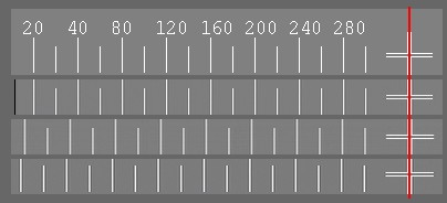
The four strips are:
- Original, cropped directly from a rip of the test DVD picture. A
DVD player outputs its 720 pixels in 53.33 µs (see below).
- Terratec Cameo Grabster, a device with a capture window of 53.33
µs.
- Hauppauge BT878a based card using the BTWincap drivers, capture
window 52.00 µs.
- Hauppauge CX23881 based card, Hauppauge drivers, capture window
is 51.56 µs.
As the capture window becomes smaller, the pixels are divided over a
smaller area and the resulting picture is stretched out horizontally!
If you want the aspect ratio to be correct on playback, you have to
correct for this effect. This page aims to give simple instructions on
how to determine what capture window your card uses utilizing standard
DVD player as a signal source.
10.2 Using the
analogue signal from a DVD player as a reference
A DVD player operates at 13.5 MHz when it plays back a DVD. In other
words, it plays back 13500000 pixels in a second. This means that a
single pixel in your MPEG2 file is played back in exactly 1/13500000 =
0.07407 µs or 74.07 ns. Note that this relationship is only valid for a standard stand-alone DVD player.
A multimedia-PC will do some scaling of it's own when generating a TV
picture and is unsuitable as a reference for determining the capture
window!
To calibrate your capture device, simply connect your DVD player to
your capture device. If possible, use an Y/C or S-video cable to do
this, but a composite video cable will do if necessary. Now play a DVD
disk, capture a small clip en see how many of the original DVD pixels
made it into your capture file. Divide the number of DVD pixels by 13.5
and you have your capture window in µs. For example, 720 DVD pixels
equals 720/13.5 = 53.33 µs.
Many DVD players will also play SVCD's. A SVCD pixel is
played back at a lower rate than DVD's, namely 9 MHz. This means that a
single pixel is played back in exactly 1/9000000 = 0.1111 µs or
111.1 ns. Because of this S-VCD pixels are 50% wider than DVD
pixels and the results will be slightly less accurate. Apart from that,
the method works just the same as for a DVD, only now you divide
by 9 instead of 13.5. For example, 480 SVCD pixels equals
480 / 9 = 53.33 µs.
There is a catch in using a DVD player as a reference source. Depending
on the brand, not all pixels on a DVD are played back. Some players
will crop pixels at the edges and output blanking signal instead.
This shows up as black vertical bars on either side in your capture.
Though this does not change the width of individual pixels, it can make
it difficult to determine how many DVD pixels
made it into the captured signal. To help with this I created a test DVD for both PAL and NTSC. You can
download these in the download
area. You need RAR to unpack
the files. DVD players can also crop off some lines at the top or
bottom and replace them with black lines, but since we are only
interested in calibrating horizontally that is not a problem.
The test DVD contains a 10 s clip in which a single frame is repeated.
This frame features vertical lines at a fixed known interval which can
be used to calibrate your capture device using the procedure below. The
DVD is set to play in a loop. Below you can see the NTSC version of the
test frame. Click it to see it full-size. The RAR files contain a ready
made VIDEO_TS folder which can be burned to video-DVD using Nero
burning Rom or any other DVD burning program. If you don't own a DVD
burner, a SVCD compliant MPEG2 file can be found here
also. Use your favorite SVCD authoring program to make a SVCD out of
it. The SVCD MPEG file contains 20 seconds of the test image shown
below (click on it to see it full size).

To be able to analyze the results with one-pixel accuracy it is
grayscale. Both DVD's and capture devices distribute color values
across two or more neighbouring pixels, which makes a color picture
difficult to use accurately. The picture contains a cross
made up of a sequence of horizontal and a sequence of vertical
perpendicular lines. The lines are spaced exactly 20 pixels apart.
Every 40 pixels, the pixel number is written next to a line. The DVD
pictures are exactly 720x480 and 720x576 pixels in size, the SVCD
pictures 480x480 and 480x576.
10.3 Capturing and how to interpret your
results
- Connect the DVD player using a good quality S-Video lead.
Composite also works, but gives less detail.
- Capture at a high horizontal size, preferably 720x480/576 or
higher, using a lossless codec like huffyuv if possible. If your
capture application won't let you do that, try VirtualVCR which can be
obtained here.
- Load the resulting AVI in VirtualDub.
- Select a clean frame and copy it to the clipboard with Ctrl+1.
- Open Microsoft paint. (Start, Programs, accessories) and paste
the picture from the clipboard Ctrl+v
- Zoom in to 800% and enable the grid (view, zoom, Custom ...., 800% and view, zoom, show grid.) The
picture below shows sections of a PAL capture made using a BT878 based
card and the BTWincap drivers v5.3.6.1 at 720x576.
|

|
The picture shows sections of a PAL capture
made using a BT878 based card and the BTWincap drivers v5.3.6.1 at
720x576. Click on the image to see the whole captured frame. |
- Search for the first visible vertical line on the left. Note the
DVD pixel number (the numbers written above the lines), i.e. 20, 40, 60
etc.The vertical line is probably composed out of 2 or more gray lines
with varying shades of gray. look for the line with the lightest shade
and note the number of pixels up to but not including it. If the
vertical line contains two lines of exactly the same shade of gray,
note the number of pixels to the left of the first of those two lines
and add 0.5. In the illustration
above the line on the leftmost position originates from DVD vertical line number 20. The vertical line with the lightest
shade of gray in the capture has 12
pixels leading up to it as indicated by the red arrow.
- Do the same for the last vertical line that is still in your
capture window on the right. In the
illustration above the line on the rightmost position originates from
DVD vertical
line number 700. The one pixel
vertical line with the lightest shade of gray in this line has 10 pixels to the right of it, as
indicated by the red arrow.
- Calculate the number of capture pixels between the two. This
number is 720 - (pixels to the left) - (pixels to the right). In the example this is 720 - 12 - 10 = 698 pixels.
- Calculate the number of DVD pixels between the lines from the
numbers printed above/below the lines. This is (Right DVD
pixel number - left number) +1. In
the example, this is 700 - 20 + 1 = 681 DVD pixels .
- From this you can calculate the ratio of DVD pixels per captured
pixel. This is (DVD pixels from step 10) / (capture pixels from step
9). In the example this number
is 681 / 698 = 0.9756 DVD pixels per captured pixel.
- Now multiply this number by the horizontal size of your
capture. In this example: 0.9756 * 720 = 702.4 DVD pixels in the
capture window.
- Divide this number by 13.5 and you have the window in µs. In the example: 702.4 / 13.5 = 52.03 µs.
Note: you might see some black
vertical bars on the left and right sides of your capture. This is
normal. Some DVD players crop a few pixels from the sides. In the
capture these show up as black pixels. These black pixels still count,
your capture is still 720x480 or 720x576 and the receipe above still
works.
The procedure when using a SVCD is identical, only at step 14 you
divide by 9 instead of 13.5.
10.4 Why are the white lines in my capture so blurred?
When you capture the DVD signal from the test DVD you will probably
notice that instead of a nice sharp single pixel wide vertical line you
get a several pixels wide line made up out of single pixel wide lines
with varying shades of grey. This has nothing to do with the
quality of your capture card. This 'blurring' is caused by the way a
DVD player plays back a single pixel. The picture below shows what
happens when a DVD player processes a single gray line with a white
pixel in it:
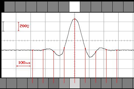
The row of squares on top represent some of the pixels in the original
line. Below that is a graph representing the part of the analogue
composite video signal resulting
from it. It was taken from an actual oscilloscope picture made from the
signal of my DVD player. When the signal goes up, the color is white.
Down is black; anything in between is a shade of gray. The peak
resulting from one pixel is actually almost three DVD pixels wide, with
oscillations at the side. Why this is so is beyond the scope of this
guide.
When you capture a signal like this using for
example a BT878 based card with BTWincap drivers at 720x576, the pixels
resulting from this will look like the row of pixels below. So the
signal resulting from a single white pixel on the DVD is smeared out
over pixels with several shades of grey in your capture. However, by
looking for the lightest pixel in your capture you can still locate
where the top of the peak is and where the original white pixel must
have been.
10.5 A special case: BT878 based capture cards
TV cards using the Brooktree/Conexant BT878 chip have been around for a
long time. As a result there are a number of specialized tools for this
chip floating around on the internet. One of them, BTtool, enables you
to read back how the chip is being programmed by the driver and the
capture application. To function, it needs a driver, BT878.sys to be
installed. Both can be found in the download
area. After installation of the driver, a reboot is required, even
if the installer does not request it.
To understand the values you use below, a short description of how
BT878 cards (and for that matter CX2388x based cards) operate is in
order. The BT878 is a programmable chip, and it is programmed by its
drivers. The drivers do this by setting registers, the digital
equivalent of switches and nobs on the chip.
First, the card digitizes the whole scanline, 64 µs, with a sample rate
of 17.73447 MHz. This yield 64 * 17.73447 = 1135 samples per
complete line (for PAL; for NTSC the number is 63.5555 * 14.31818
= 910 pixels). These 1135 samples are reduced to the required number of
samples per line by interpolation. In other words, the original samples
are sampled again, but at a lower rate resulting in the desired reduced
number of pixels per line. The amount of reduction is set by a scaled
sampling rate. The HScale register contains the ratio
between the unscaled and the scaled sample ratio.
Because a whole line contains non-picture information on the left
(horizontal blanking) and for a short stretch on the end (Front Porch)
the resulting pixels have to be cropped to obtain the required number
of pixels. The HDelay register determines how many of
the scaled pixels are to be cropped on the left. The HActive
register determines hor many pixels after that are used. Any
pixel left after HDelay and HActive is ignored.
More on how the scaler in a capture device operates can be found here.
More details on the BT878 registers can be found in the DataSheet.
You can determine the capture window of a BT878 based device as follows:
Warning! The BTtool and driver can
make your system unstable while they are running. Please do not run any
other applications while testing to prevent data-loss!
- Do not start BTtool yet!
- Open your capture application, set the capture size and
enable the preview.
- Start BTtool and write down the following hexadecimal
numbers which can be found in the upper left corner of the BTtool
screen:
- Crop
- Vactive Lo
- HDelay low
- HActive Lo
- Hscale Hi
- HScale Lo
- Select your TV system and fill in the numbers in the calculator
provided below.
- Press the Compute button
Warning: Do not change your capture
settings while BTtool is running! First close BTtool, make your
changes, and restart BTtool afterwards.
Example: The picture shows the BTtool
readings for the PAL 720x576 capture on a BT878 based card with
BTWincap drivers from the example used in the previous section. These
values have already been set as defaults in the calculator below. Press
Compute to see the results.

In our example, the HScale setting
results in a scaled sampling rate of 13.849 MHz. This results in 13.849 *
64 = 886 scaled pixels per
line.
These lines of pixels still
contain the horizontal blanking information before the active
video area begins. So HDelay sets the number of pixels at the start
which must be cropped, 143 in
the example. The final register is HActive, which sets the number
of pixels following HDelay which hopefully contain
the picture. HActive will normally be the number of horizontal pixels
you chose for the capture, and in this case is 720. Once these 720 pixels are in,
the final 886 - 143 - 720 = 23 pixels are skipped.
From this information, the capture window can be determined:
The capture window now is 720 /
13.849 = 51.99 µs. This
equals 51.99 * 13.5 = 701.9 DVD pixels.
References:
Digital Video Resolutions: A Quick Guide to Digital Video Resolution and
Aspect Ratio Conversions.
Video
Formation,
Perception and Representation (pdf file): by Y Wang.
Der
Karl's Capture Karten aspect ratio fuer Dummies: Der Karl's Capture Card
Aspect Ratio for Dummies (in German).
Capture-Cards
and aspect-ratio for Dummies: Der Karl's Capture Card Aspect Ratio for
Dummies (translated by Arachnotron).
Introduction
to digital aspect ratio conversion (White paper at Snell & Willcox)
Back to the Index: HOME
English version last edited on: 06/13/2004 |
First
release: n/a | Author: Arachnotron | Content by Doom9.org

