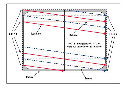
A TV signal consists of the even lines (which forms the even field)
which are shown first, followed by the odd lines (which forms the odd
field). These lines are called scan lines. When a pulse of
a certain shape in the signal occurs, the TV knows a line has ended and that the
beam should travel back to the other edge of the screen to start drawing a new
one. This is called horizontal retrace. The fields are shown
with a speed of 50 fields per second (PAL/SECAM) and 59.94 fields per second
(NTSC). The fields are separated by vertical blanking interval lines
(abbreviated: VBI lines) that are not drawn on your TV. These lines
don't contain any picture
data. Some are needed for synchronization of the TV set. Since it is
known what is in these lines, there is no reason to store them
and they are cropped of by the capture device and are recreated
upon playback by your DVD/VCD player. A lines which contain picture data is
called an active line. This way of showing video is called interlacing,
and all analogue signals have it. Depending on the source you may not see it in
a capture, but it is always present in the signal (see figures 1-3).
A single PAL line takes 64 µs (= microseconds = 1 / 1000000
second) to complete. Also in this case, not the whole line consists of picture
information. The ITU-R BT470 specification states that the active part of a
PAL line should be about 52 µs. For NTSC, it takes 63.556 µs with
active part of about 52.6555 µs (1). The rest of the line contains
synchronization information on either side of the active part, known as
horizontal blanking.
A set of two fields is called a frame. The terms frame and field are both used
to describe a raw set of scan lines including blanking and only the active
part of it carrying picture information. PAL/SECAM has 25 frames
per second (and 625 lines) and NTSC has 29.97 frames per second (and 525 lines).
|
| figure 1: Interlaced scanning system (source: Composite/CVBS Interface) |
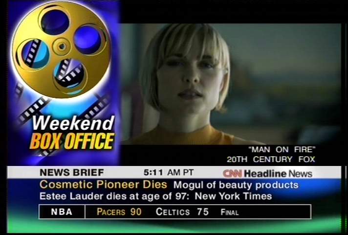
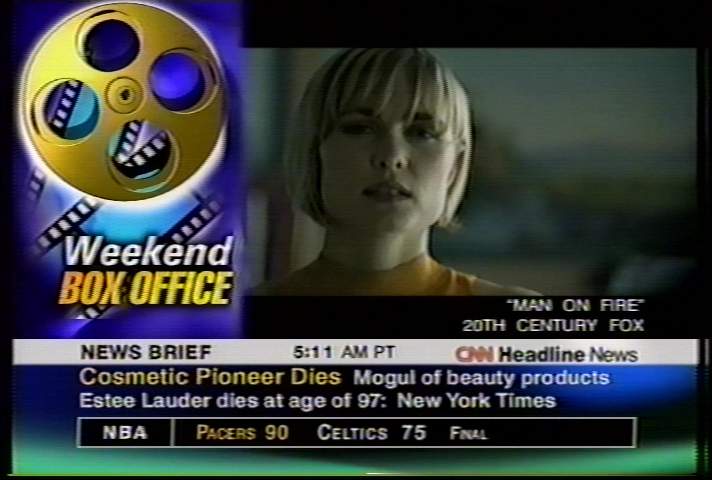
The following two figures show two successive fields. In this example, you can clearly see that the white and red balls are moving, and the fields are snapshots from different points in time. This is what you will see on your television and it is called interlaced playback.
 |
 |
| figure 2: odd field | figure 3: even field |
However, the two fields are merged after capturing and the image is called interlaced (see figure 4).
 |
| figure 4: combined field (= frame) |
In the sections 7.1 postprocessing with VirtualDub and 7.2 postprocessing with AviSynth will be discussed how to deal with this.
For those who are interested, a more detailed description of the workings of analogue video is given in section 9.
This subsection is concluded by a summary of the PAL/NTSC standards. Since TV transmission is analogue, there are no pixels, but only lines. A PAL system contains 625 lines which make the picture. Each of these lines take 64 µs to be drawn on your TV. NTSC contains 525 lines, and takes 63.555 µs each line. The active picture you see is only contained in a portion of this signal. The rest is for synchronization. (Therefore, capture cards only capture/sample a portion of this signal.)
The PAL/NTSC Standards Review
More information on these standards can be found in section 9.
References:
Display Devices:
Composite/CVBS
Interface: Explains the workings of analogue video.
Temporal rate and
its history: About interlacing and its origin.
ITU-R
BT.470-5 recommendation: About the PAL/SECAM/NTSC standards.
A capture device digitizes the analogue signal. This is done by
measuring the signal at a fixed time interval and recording the value
as a binary number. The rate at which this happens is called the sample
rate. Video is typically sampled many millions of times a second, or
MHz (= megahertz, or 1000000 samples per second).
The capture card samples at a fixed sample rate and the driver resizes the
picture afterwards. If you set a PAL capture size of 704x576 in VirtualVCR, the
capture device will first digitize all lines at a high sample rate. It
will then proceed to crop off all the VBI lines. Next it will crop
off the horizontal blanking and the front porch, leaving 52
µs of samples per line which contains the video
information. Then it will use the samples from this part of the line to
calculate the required 704 pixels. The result is two fields of
704x288. Finally it will weave together the two fields and pass on the
finished 704x576 picture to VirtualVCR.
You now have 52 µs of analogue signal, contained in 704
pixels. This makes your final sample rate 704 samples / 52 µs
= 13.54 MHz. The more detail there is in the picture, the more pixels
you need to see it. More pixels means a higher size, and so a
higher sample rate is needed.
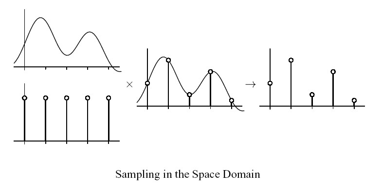 |
| figure 5: the sampling process |
source: Basic Signal Processing
References:
ITU-R
BT.601-5 recommendation: The guideline for converting
analogue signal into computer pixels.
An analysis of sampling and
filtering: About why a pixel is not a little square, but just a point
sample.
All analogue sources output 576 active lines per frame (PAL) or 480 active lines per frame (NTSC). Capture devices process line by line into pixels, so one line becomes one row of pixels. Because of this, only two vertical sizes are suitable for capturing: full and half: 576 and 288 (PAL) or 480 and 240 (NTSC). Any other size will cause the device to cap all lines anyway and resize them afterwards. Since vertical resizing by capping devices in general gives very ugly results you should not do this. When you cap at half vertical size, capping devices just discard every second field. (Note: the official NTSC vertical resolution is 486, but all capture devices crop this to 480 lines.)
If you are new to the capturing process, you are advised to skip the following subsections and proceed with section 4. However if you know how to capture, and you want to know more about bandwidth, you should read this subsection. In the analogue world, there are pixels nor sizes. The term bandwidth describes the theoretical maximum amount of detail that can be reproduced for a given medium. If you have a VHS VCR connected to your TV set, you will probably have noticed the recording never looks as sharp as the original broadcast. The cause has to do with bandwidth: a VHS tape has a lower bandwidth than a TV signal, so you loose some of the fine detail. Likewise a SVHS tape has a lower bandwidth than a TV signal, but higher that a VHS tape. Like sample rate, bandwidth is also given in MHz, or millions of changes per second. The difference in bandwidth between TV, SVHS and VHS can easily be seen in the following screenshots:
|
|
|
figure 6: source: 712x480 cap from TV |
|
| figure 7: source: 712x480 cap from SVHS |
|
|
|
figure 8: source: 712x480 cap from VHS |
As can be seen, the screenshot from VHS also contains some cross color
artefacts (chroma noise in the text for example). More about this in the Removal
of chroma artefacts section. Btw, have a look at the vertical lines in the girls
collar on the TV cap (which are not present in the SVHS and VHS screenshots).
The more fine detail there is in a picture, the more rapidly the video
signal has to change to describe it. Suppose you are looking at a close
up of a black and white pinstripe shirt with 500 black and white
lines in the shot. The video signal has to change very fast between
black and white to describe this. You have 250 black/white cycles in
your 52 µs video line or 250 / 52 µs = 4.8 MHz.
PAL/SECAM Television broadcast typically has a bandwidth of 5 - 5.5 MHz
depending on your country. The shirt shot would not pose any problems,
and if you watched it on TV you would be able to count the single
lines. But if you taped it to ordinary VHS tape, which has a bandwidth
of 3-3.4 MHz, the detail would be gone and on playback you would see a
solid gray shirt. You might still recognize the buttons, but the fine
stripes would be blurred. Now suppose the camera zooms in very closely
on the same shirt until you have two vertical black and white lines
filling the whole screen. A single video line now has
to change twice from white to black to white and to black again in 52
µs
(PAL) to describe this. The bandwidth needed for this low amount of
detail is only 2 / 52 µs = 0.04 MHz. Taping this
shot on VHS would not pose a problem.
So, the finer the detail in your picture, the higher the bandwidth you
need to see it without blurring.
The bandwidth of an analogue source can be found in the manual of your
source. Sometimes measure called lines of (horizontal) resolution
is given. It is defined by the number of side by side dots that can be
reproduced within a scan line. To get the bandwidth, divide
the number of lines by 78 (2) for PAL (79 (2) for
NTSC)
and you have the bandwidth in
MHz. For example: NTSC
broadcast has 330 lines of resolution, which equals 330/79 = 4.2 MHz.
However, this is the theoretical minimum. In practice, there are some issues which imply that you need about three times the bandwidth (this is explained in more detail in section 5). Thus, for you VHS source, you need about 3 x 3.0 x 52 = 468 pixels per line (say 480x576) to keep all detail.
Either bandwidth or "lines of resolution" can be found in the specifications of various video equipment. The table below gives the "lines of resolution", bandwidth, minimal sample rate and minimal horizontal resolution needed for various analogue sources. The sizes are rounded to the next multiple of 8 and can be used for PAL, SECAM and NTSC targets.
| Source | lines of resolution | Bandwidth (MHz) | Minimal sample rate (MHz) | Minimal horizontal size (pixels) |
| TV (1) | 330 | 4.2 | 8.4 | 440 |
| TV (2) | 390 | 5.0 | 10.0 | 520 |
| TV (3) | 430 | 5.5 | 11.0 | 576 |
| TV(4) | 470 | 6.0 | 12.0 | 624 |
| Laser disk | 450 | 5.8 | 11.6 | 600 |
| S-VHS(-C) SP/LP | 400 | 5.0 | 10.0 | 520 |
| S-VHS EP | 350 | 4.7 | 9.4 | 472 |
| VHS(-C) SP/LP | 235 | 3.0 | 6.0 | 312 |
| VHS EP | 220 | 2.6 | 5.2 | 296 |
| Betamax / Beta 1 | 250 | 3.2 | 6.4 | 336 |
| Betamax / Beta 2,3 | 235 | 3.0 | 6.0 | 312 |
| SuperBeta | 280 | 3.6 | 7.2 | 376 |
| Betacam | 315 | 4.0 | 8.0 | 424 |
| Super Betacam | 390 | 5.0 | 10.0 | 520 |
| ED Beta | 500 | 6.4 | 12.8 | 672 |
| M-II | 340 | 4.4 | 8.8 | 456 |
| 8mm / Video8 | 255 | 3.3 | 6.6 | 344 |
| Hi 8 | 430 | 5.5 | 11.0 | 576 |
| U-matic | 280 | 3.6 | 7.2 | 376 |
| U-matic SP | 330 | 4.2 | 8.4 | 440 |
| V2000 | 240 | 3.1 | 6.0 | 320 |
| (1)
NTSC/M, PAL/N (2) PAL/SECAM B,G and H (3) PAL/SECAM I (4) PAL/SECAM D, K, K1 and L |
||||
As you can see CVD (352x576 / 352x480) and VCD (352x288 / 352x240) have a to low horizontal size (besides the reduced vertical size for VCD) to do justice to most analogue sources. Some may get by on S-VCD, but many require full DVD resolution to loose no detail.
References:
ITU-R
BT.470-5 recommendation: If you register, you can download three
ITU
recommendations for free!
PAL Site - The home of the
PAL videosystem
An
introduction to VCRs
Sencore
TechTip 189: Comparison of tape formats
Bandwidth: Horizontal
and vertical resolution for television and video.
Leopold's Home
Video Formats Page: Some information on various video formats.
TV and Video Resolution:
Horizontal and vertical resolution for television and video.
Footnotes:
(1) There are actually several NTSC standards with 52.6555
µs being one of them (ITU-R BT.470-6, EIA RS-170A). Two others are 53.07
µs (FCC 73.699) and 52.86 µs (SMPTE 170M-1999). Notice that ITU and EIA give the same number, but measure it on a
different point. The difference is roughly equal to the build-up time. We don't
how to find out which standard is used. Therefore the standards with an active NTSC
picture is assumed in this guide.
(2) The number of lines you can put in 1 MHz of bandwidth: for PAL: 2 * 1 MHz *
52 µs / 1.3333 = 78 lines of resolution, and for NTSC: 2 * 1 MHz * 52.6555 µs /
1.3333 = 79 lines of resolution.
Next: Capture sizes for newbies or Capture sizes for advanced users.
Back to the Index: HOME
English version last edited on: 06/13/2004 | First release: n/a | Authors: Version4Team | Content by Doom9.org